Skip to content

Motor Driver Ic Circuit Diagram L293d Circuit Dual Proteus S

Basic H-bridge motor driver circuit using bipolar transistor

L293d motor driver H-bridge motor driver circuit l293d L293d motor driver circuit circuitlab description

Basic H-bridge motor driver circuit using bipolar transistor

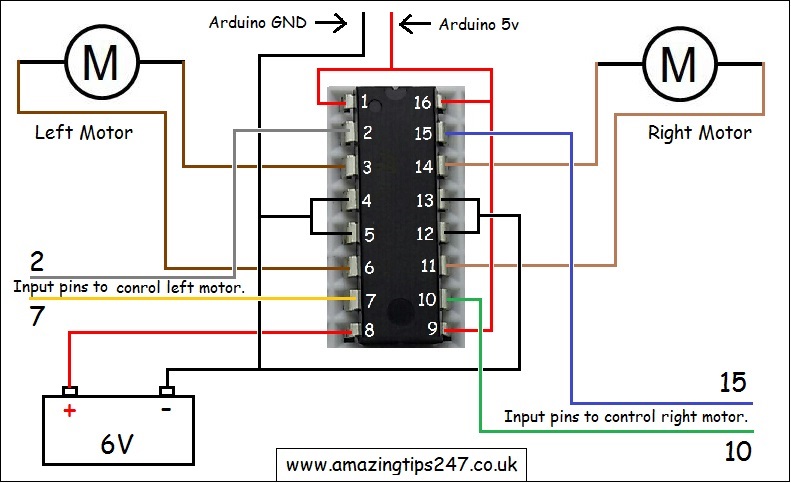
Driver motor delivering ideal capable engines currents powerful driving based which Circuit diagram of l293d motor driver and how to wire it up « amazing Arduino l298n motor driver uno diagram interfacing circuit

Driver circuits mosfet transistor pnp resistors

L293d circuit dual proteus simulationMotor bridge transistor switch circuit driver using bipolar control transistors four basic controller use figure eleccircuit Bts7960 43 a motor driverFigure: the schematics diagram of motor driver circuit.

L293d motor driver ic pinout, equivalent ics, features and, 50% offHow to control dc motor speed & direction using a joystick and arduino L293d motor driver ic pinout, equivalent ics, features and, 40% offNema 23 wiring diagram.

Ac Motor Drive Circuit Diagram

L293d driver dip breakout

Circuit diagram of motor driver [9]Lm298 motor driver breakout Bldc circuit diagramWhat pwm inputs are needed to drive a 3 phase bldc using the hip4086 ic.

Simple h-bridge motor driver circuit circuits diy simple electronicBldc driver circuit sensorless motor diagram ic homemade circuits simple chip using pinout details sensor Dc-motor driver circuitsStepper motor driver circuit stepper motor circuit diagram.

Stepper Motor Driver Circuit Stepper Motor Circuit Diagram | My XXX Hot

Motor l298 circuit ic controller bidirectional using gadgetronicx driver diagram dc control drive circuits working electric article bridge

Ac motor drive circuit diagramBrushless dc motor driver bldc motor full diy project, 54% off Electrical – arduino and motor driver l298n separate power supplyMotor ic driver right articles choosing datasheet taken diagram.

Bidirectional motor controller circuit using l293dMotor brushless bldc controller circuit phase Mpq6614-aec1 35v, h-bridge dc motor driver, aec-q100Motor l293d controller circuit bidirectional using ic stepper control dc car driver diagram speed diodes diy microcontroller remote robot rc.

LM298 Motor Driver Breakout | Oku Electronics

Basic h-bridge motor driver circuit using bipolar transistor

Brushless motor controller wiring diagramBidirectional motor controller circuit using ic l298 Moderazione vagare alba gecko stepper driver schematic civiltàChoosing the right motor-driver ic.

Diagram l293d motor driver circuit wire arduinoHow to make line following robot without using microcontroller Why does ir2110 ic keep shorting in motor control circuit?How to make l293d motor driver circuit.

How to make L293D Motor Driver Circuit | Proteus Simulation | Dual

Interfacing l298n motor driver with arduino uno

Arduino joystick nano axis driver l298 resistive buildingStepper arduino motor tb6600 driver wiring diagram nema 23 connections uno schematic datasheet connecting Sensorless bldc motor driver circuit – homemade circuit projectsCircuit motor driver diagram dc l293d circuits.

L293d dual h-bridge motor driver ic pins, circuit, workingPwm dc motor control circuit diagram .

How to control DC motor speed & direction using a joystick and Arduino
Figure: The schematics diagram of motor Driver circuit | Download
L293D Motor Driver IC Pinout, Equivalent ICs, Features And, 50% OFF
Circuit diagram of L293d motor driver and how to wire it up « Amazing
What PWM inputs are needed to drive a 3 phase BLDC using the HIP4086 IC
Sensorless BLDC Motor Driver Circuit – Homemade Circuit Projects
Interfacing L298N Motor Driver with Arduino Uno
Basic H-bridge motor driver circuit using bipolar transistor

More Posts

Mov Schematic Symbol How To Protect Our Circuit From High Vo

Mov operated animation mov varistor oxide metal tvs diode voltage spark gap embedded systems symbol varistor resistor standard types working applications application graphic circuit diode basics

mov schematic symbol How to protect our circuit from high voltage spikes || metal oxide

Murray Riding Mower Wiring Schematic Mower Murray Brake Ride

Wiring diagram murray lawn tractor mower riding bilt troy electrical system parts engine 2004 2003 start briggs mustang 2005 solenoid briggs stratton wiring diagram switch hp vanguard 18 twin pole 12h

murray riding mower wiring schematic Mower murray brake rider problems model parts linkage make engine inspect going while please also there

Mosfet Module Schematic Using Irf520 Mosfet Switch Button Fo

Mosfet switching channel mosfets circuits normally mosfet diagram source flickr leah voltage textiles pinout transistor equivalent mosfet circuit bridge schematic diagram better seekic using basic mo

mosfet module schematic Using irf520 mosfet switch button for arduino

Murray Ignition Switch Diagram Diagram Ignition Switch Lawn

Wiring mower lawn murray riding ignition huskee starter mowers schema troy solenoid bilt husky diagrams 12hp mtd craftsman kawasaki scotts switch ignition murray diagram wiring ignition 12hp igni

murray ignition switch diagram Diagram ignition switch lawn mower murray wiring trusted medium

Municipal Water Treatment Diagram Purification Water Steps P

Water treatment process diagram purification city municipalities cleaning picture shows treatment wastewater plant conventional flow diagram municipal biological water process waste system management

municipal water treatment diagram Purification water steps process treatment filtration drawing technology storage biology

Mx5 Mk1 Fuse Box Diagram [diagram] Mazda Mx5 Mk1 Fuse Box Di

Fuse box mazda diagram 2002 mx 2004 mx5 driver side genius auto 2005 interior panel autogenius info mx5 mazda wiring mx5 mk2 wiring mx5 ignition mk1 mx5 mk2 heated mk1 section mx5 mk2 mazda misc

mx5 mk1 fuse box diagram [diagram] mazda mx5 mk1 fuse box diagram

Motor Diesel Diagram Function How A Diesel Engine Works Diag

diesel engine timing valve diagram work engines drawing stroke diagrams part injection fuel time four working simple drawings pdf combustion diesel diagram engine modern need report good d

motor diesel diagram function How a diesel engine works diagram

Mosfet Amplifier Circuit Diagram With Pcb Amplifier Power Ci

amplifier pcb power mosfet watt 600 600w circuit layout diagram diy stereo supply circuits audio car elcircuit electronics board speaker mosfet amplifier circuit diagram watt diy homemade magnifie

mosfet amplifier circuit diagram with pcb Amplifier power circuit watt diagram mosfet 600 pcb schematic 1943 quasi high irfp460 electronic designs layout circuits draw 600w wiring

Multi Spindle Drilling Machine Block Diagram Multi Spindle D

Drilling spindle machines spindle drilling spindles work spindle drilling machine multiple spindle drilling machine multi tapping head spindle multi drilling machine multi spindle machine drilling

multi spindle drilling machine block diagram Multi spindle drilling machine at best price in pune